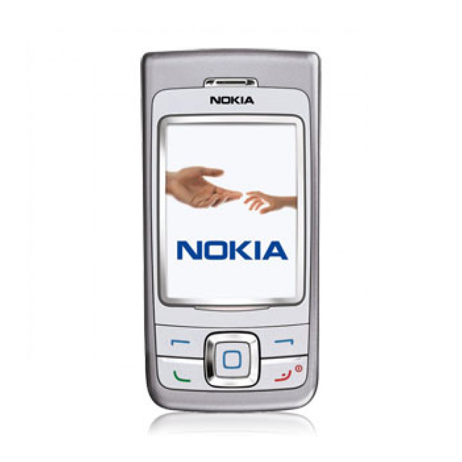
Nokia 6265 Reassembly
Mobile terminals
Hide thumbs
Also See for 6265:
- User manual (257 pages) ,
- Rf description and troubleshooting (84 pages) ,
- Baseband description and troubleshooting (60 pages)
Summary of Contents for Nokia 6265
- Page 1 Nokia Customer Care 6265/6265i/6268 (RM-66) Mobile Terminals Reassembly ©2005 Nokia Corporation Issue 1 11/2005 Company Confidential...
-
Page 2: Table Of Contents
6265/6265i/6268 (RM-66) Reassembly Contents Page Safety Information ............................3 ESD Protection ............................. 3 Reassembly Instructions ..........................4 1. Insert the DC Jack ........................... 4 2. Insert the Camera Flash ........................4 3. Insert the BT Antenna ..........................4 4. Insert the IHF Assembly ........................5 5. -
Page 3: Safety Information
• Every repair action involving opening the phone or handling the phone components must be done under ESD protection. • ESD-protected spare part packages MUST NOT be opened/closed outside an EPA. For more detailed information about ESD protection and EPAs, contact your local Nokia Customer Care representative. ©2005 Nokia Corporation... -
Page 4: Reassembly Instructions
6265/6265i/6268 (RM-66) Reassembly Reassembly Instructions 1. Insert the DC Jack Using a CA-44 adapter, gently press the DC-Jack into the D-cover assembly. Make sure the adapter is not plugged into an electric source. CA-44 adaptor 2. Insert the Camera Flash Gently place the camera flash into its retainers and snap it into place using your fingers. -
Page 5: Insert The Ihf Assembly
6265/6265i/6268 (RM-66) Nokia Customer Care Reassembly 4. Insert the IHF Assembly Grasp the IHF assembly with the inside facing you. Insert it, pushing toward the bottom of the D-cover. Rotate and snap it into position within the D-cover assembly. Make certain not to damage the IHF speaker gasket during assembly. -
Page 6: Insert The Lcd Flex Cable And Assembly
6265/6265i/6268 (RM-66) Reassembly 6. Insert the LCD Flex Cable and Assembly a. Fit the LCD display into the LCD frame, carefully aligning the mounting tabs. Gently press into place from the back to secure. b. Place the UI PWB into the B/C slide assembly making sure the alignment pin is visible. -
Page 7: Insert The Main Flex Assembly
6265/6265i/6268 (RM-66) Nokia Customer Care Reassembly d. Connect the LCD to the UI PWB by pressing together. 7. Insert the Main Flex Assembly a. With the slide assembly open, align both UI flex slots. Insert the flex through the two slots. Place the keymat on the frame. Align and connect the flex cable. -
Page 8: Add The Screws
6265/6265i/6268 (RM-66) Reassembly 8. Add the Screws With the main flex assembly secured, fasten the four IP-4 Torx 4 Plus screws. Use torque driver set to 11Ncm. 9. Camera Installation Using the SS-45 camera removal tool, place the camera module into position in the camera mount using the alignment tab. -
Page 9: Attach The Pwb And B/C Slide Assembly
6265/6265i/6268 (RM-66) Nokia Customer Care Reassembly 10. Attach the PWB and B/C Slide Assembly a. Place the PWB into the D-cover using the alignment pins. b. With the mobile terminal slide assembly open, align and connect the main flex cable through the keymat hole. -
Page 10: Add The Screws
6265/6265i/6268 (RM-66) Reassembly 11. Add the Screws With the slide assembly open, fasten the four IP-4 Torx 4 Plus screws in the order shown below. Use torque driver set to 15 Ncm. 12. Connect the A-cover and the B-cover a. With the mobile terminal slide assembly open, rotate the A-cover into position on the slide assembly and snap it into place. -
Page 11: Add The Camera Gasket
6265/6265i/6268 (RM-66) Nokia Customer Care Reassembly Complete the step by affixing the screw caps. Caution: Make sure the mini-SD door is open before placement. Do not close SD door until A-cover is screwed down. 13. Add the Camera Gasket Gently place the camera gasket onto the camera lens barrel and press it into place. -
Page 12: Attach The Antenna/E-Cover
6265/6265i/6268 (RM-66) Reassembly 14. Attach the Antenna/E-cover Carefully align the E-cover to the D-cover assembly. Press the E-cover into place by gently squeezing all sides to ensure a tight fit. 15. Attach the Main Keymat a. Gently insert the left side of the keymat into the C-cover assembly, tucking it between the cover and the keydome sheet. -
Page 13: Insert The Battery And Attach The Battery Cover
6265/6265i/6268 (RM-66) Nokia Customer Care Reassembly 16. Insert the Battery and Attach the Battery Cover a. Insert the battery. a. Slide the battery cover into position and press to snap it into place. ©2005 Nokia Corporation Issue 1 11/2005 Company Confidential... - Page 14 6265/6265i/6268 (RM-66) Reassembly Nokia Customer Care This page intentionally left blank. ©2005 Nokia Corporation Page 14 Company Confidential Issue 1 11/2005...


