Table of Contents
Advertisement
Quick Links
Advertisement
Table of Contents

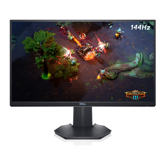
Summary of Contents for Dell S2421HGFB
- Page 1 Simplified Service Manual–S2421HGFB Version: 01 Date:2021/03/04...
-
Page 2: Table Of Contents
Content Index 1. General Safety Instructions ..................3 1.1 SAFETY: General Safety ..................3 1.2 SAFETY: General Power Safety ................5 2. Exploded view diagram with list of items ..............6 3. Wiring connectivity diagram ..................7 4. Disassembly and Assembly Procedures ..............8 4.1 Disassembly SOP .................... -
Page 3: General Safety Instructions
IMPORTANT NOTICE FOR USE IN HEALTHCARE ENVIRONMENTS: Dell products are not medical devices and are not listed under UL or IEC 60601 (or equivalent). As a result, they must not be used within 6 feet of a patient or in a manner that directly or indirectly contacts a patient 1.1 SAFETY: General Safety... - Page 4 When operating your equipment: Do not use your equipment in a wet environment, for example, near a bath tub, sink, or swimming pool or in a wet basement. Do not use AC powered equipment during an electrical storm. Battery powered devices may be used if all cables have been disconnected.
-
Page 5: Safety: General Power Safety
socket. If your equipment uses an AC adapter: Use only the Dell provided AC adapter approved for use with this device. Use of another AC adapter may cause a fire or explosion. NOTE: Refer to your system rating label for information on the proper adapter model ... -
Page 6: Exploded View Diagram With List Of Items
2. Exploded view diagram with list of items Item Description Q'ty ASSY BZL CHIN Panel MYLAR PWR PCBA I/F BD PCBA SPS BD ASSY SHD MAIN ASSY RC ASSY CLMN ASSY BASE PCBA CTRL BD PCBA CTRL+KEY BD BTN-PWR PCBA CTL LENS BD Power cable HDMI cable... -
Page 7: Wiring Connectivity Diagram
3. Wiring connectivity diagram FFC 1 FFC 2 Wire 1 FFC 3 FFC 4 - 7 -... -
Page 8: Disassembly And Assembly Procedures
4. Disassembly and Assembly Procedures 4.1 Disassembly SOP Preparation before disassemble 1. Clean the room for disassemble 2. Identify the area for monitor 3. Check the position that the monitors be placed and the quantity of the monitor; prepare the area for material flow;... - Page 9 1. Use hands or Scraper bar scraper bar to disassemble Rear Cover from monitor Notice the disassembly order: Top Side=>Right/ Left Side=>Bottom Side 2. Remove CTRL BD FFC wire from I/F BD and remove all tapes from panel 1. Remove PWR BTN Philips-head BD FFC wire from screwdriver...
- Page 10 1. Remove Mylar from SPS BD 1. Unlock 8 PCBA Philips-head screws screwdriver (Torsion of screw: 8.5±1.0kg) 1. Disassemble I/F BD from Main SHD and remove SPS BD wire from I/F BD 2. Remove two LVDS FFC cable from I/F 3.
-
Page 11: Assembly Sop
4.2 Assembly SOP Preparation before assemble 1. Clean the room for work 2. Identify the area for material 3. Prepare the implement, equipment, material as bellow: 1) Working table 2) Philips-head screwdriver 3) Glove 4) Cleaning cloth ESD protection Item Picture Operation Tools... - Page 12 1. Insert two FFC LVDS cable to panel 2. Paste 1 yellow tape and then paste 1 AL foil on yellow tapes 3. Insert Backlight wire to SPS BD and paste 1 tape to fixed Backlight wire on panel 1. Locate Main SHD to panel and Philips- lock 4 screws head...
- Page 13 Lock 4 RC screws Philips- head screwdriver (Torsion of RC screw: 8~10Kg) To attach the monitor stand: 1. Align and place the stand riser on the stand base. 2. Open the screw handle at the bottom of the stand base and turn it clockwise to secure the stand assembly.
-
Page 14: Trouble Shooting Instructions
5. Trouble shooting instructions - 14 -... - Page 15 - 15 -...
- Page 16 - 16 -...
- Page 17 - 17 -...
- Page 18 - 18 -...
- Page 19 - 19 -...
- Page 20 - 20 -...


