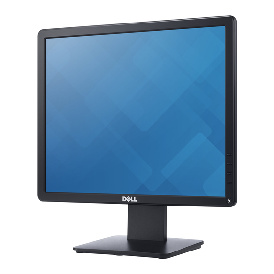
Dell E1715S Service Manual
17" lcd monitor
Hide thumbs
Also See for E1715S:
- Service manual (22 pages) ,
- Disassembly (8 pages) ,
- User manual (1 page)
Advertisement
Quick Links
Advertisement

Summary of Contents for Dell E1715S
- Page 1 17" LCD Monitor Dell E1715S Service Service Service Simplified...
- Page 2 Accordingly, a servicer who uses a service procedure or tool which is not recommended by DELL must first satisfy himself thoroughly that neither his safety nor the safe operation of the equipment will be jeopardized by the service method selected.
- Page 3 Exploded view diagram with list of items...
- Page 4 Description Q’ty LOGO DELL BEZEL KEY_FUNCTION KEY_POWER KEY BOARD PANEL INSULATING SHEET POWER INSULATING SHEET MAINFRAME KNOB_CONTROL Part No. Description Q’ty MAINFRAME 0Q1G6019 1 SCREW (KEY BOARD-BEZEL) REAR_COVER 0Q1G 130 6 47 CR3 SCREW (KNOB_CONTROL) STAND-BASE ASS'Y 0M1G3030 4 47 CR3...
- Page 5 Wiring connectivity diagram This Connector welding Connector Ass’y PN: in Key Board 395G179W30B51200HF Connector Ass’y PN: Connector Ass’y PN: 395G801406RJ6000HF 395G082509D53000HF...
- Page 6 3. Mechanical Instruction Tools Required List the type and size of the tools that would typically can be used to disassemble the product to a point where components and materials requiring selective treatment can be removed. Tool Description: − Screwdriver (Phillip-head, Hexagonal head) − Penknife ...
- Page 7 3.1 Disassembly Procedures: Step Figure Remark Turn off power, S1. Before Unplug external disassemble cables from product To remove the stand: 1. Wedge your fingers Press and hold the stand release button. 2. Lift the stand up and away from the monitor. S2.Remove the STAND-BASE ASS’Y...
- Page 8 Use a Philips-head screwdriver to remove 2 screws for unlocking mechanisms. (No.1~2 screw size=M3x4; Torque=4±1kgf.cm) S3.Remove the REAR COVER Use Penknife to separate the bezel and rear cove follow the arrows in sequence, then you can take out rear cover. S4.Disconnect the connectors,and tear off the tapes...
- Page 9 Use a hex screwdriver to remove 2 screws for S5.Unscrew the unlocking mainboard. hex screws (No.1~2 is Hex-screw, Torque= 4.5±0.5kgf.cm) Use a Philips-head screwdriver to remove 5 screws for unlocking S6.Unscrew the mainboard. screws to remove (No.1~4 screw the Main board and size=M4x8;Torque= Power board 6±1kgf.cm;...
- Page 10 Use a Philips-head screwdriver to remove 1 S9. Remove the screw for unlocking clip. screw (No.1 screw size=Q3x6; Torque=4±1kgf.cm) The MAIN FRAME...
- Page 11 3.2 Assembly Procedures: Step Figure Remark Use a Philips-head screwdriver to screw 1 screw for tighten the clip S1. Tighten the clip (No.1 screw size=Q3x6; Torque=4±1kgf.cm) Use a Philips-head screwdriver to screw 3 screws for tighten Key S2.Assembly the board. KEY BOARD (No.1~3 screw size= M2x2.5...
- Page 12 Use a Philips-head screwdriver to screw 5 screws for tighten S4.Sscrew the mainboard. screws to tighten (No.1~4 screw the Main board and size=M4x8;Torque= Power board 6±1kgf.cm; No.5 screw size=D3x6;Torque= 6±1kgf.cm) Use a hex screwdriver to screw 2 screws for S5.Screw the tighten mainboard.
- Page 13 Use a Philips-head screwdriver to screw 2 screws for tighten S6.Assembly the mechanisms. REAR COVER (No.1~2 screw size=M3x4; Torque=4±1kgf.cm) S7.Assembly the STAND-BASE ASS’Y ...
- Page 14 Trouble shooting instructions ...
- Page 19 ...


