Sign In
Upload
Manuals
Brands
Dell Manuals
Storage
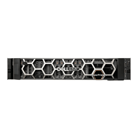
PowerProtect DD6900
Dell PowerProtect DD6900 Manuals
Manuals and User Guides for Dell PowerProtect DD6900. We have
1
Dell PowerProtect DD6900 manual available for free PDF download: Manual
Dell PowerProtect DD6900 Manual (149 pages)
Brand:
Dell
| Category:
Storage
| Size: 3.25 MB
Table of Contents
Table of Contents
2
Figures
7
Tables
10
Chapter 1: FRU and Upgrade Overview
12
Tools and Supplies Needed
12
Safety Overview
13
Safety Instructions
13
Establish a Serial Management Connection to the Powerprotect System
14
Establish a Serial Connection to the Serial Port
14
Maintenance Connections
14
Communications Settings
14
Establish an SOL Connection
15
Component Characteristics
15
Prepare HA Systems for Component Replacement
15
Chapter 2: Replace an Operating System Disk
17
Identify a Failed os Disk
17
Remove the Front Bezel to Access Front Panel Hard Drives
18
Drive Fault LED
18
Remove a Hard Drive
19
Removing the Front Bezel
19
Removing a Hard Drive
19
Install the Hard Drive
20
Install the Front Bezel
20
Installing a Hard Drive
20
Verify the Replacement Drive
21
Installing the Front Bezel
21
Drive Fault LED
21
Chapter 3: Replace a Cache Tier Disk
23
Chapter 4: Replace a Fan
24
Identify a Failed Fan
24
Extend the System from the Cabinet
25
Remove the System Cover
25
Remove the Cooling Fan
26
Install the Cooling Fan
26
Remove the System Cover
26
Removing Cooling Fan
26
Install the System Cover
27
Installing Cooling Fan
27
Slide the System into the Cabinet
28
Verify the Replacement Fan
29
Restore the HA Configuration
29
Chapter 5: Replace a Power Supply
31
Identify a Failed Power Supply
31
Remove a Power Supply
32
Install the Power Supply Unit
33
Verify the Replacement Power Supply
33
Restore the HA Configuration
34
Chapter 6: Replace the Network Daughter Card
35
Verify the Status of the Network Daughter Card
35
Shut down and Disconnect the System
36
Extend the System from the Cabinet
36
Remove the System Cover
37
Removing the Air Shroud
38
Remove Expansion Card Riser 2
38
Remove the Network Daughter Card
39
Install the Network Daughter Card
39
Removing Expansion Card Riser 2
39
Removing the Network Daughter Card
39
Install Expansion Card Riser 2
40
Installing the Network Daughter Card
40
Installing Expansion Card Riser 2
40
Installing the Air Shroud
41
Install the System Cover
41
Slide the System into the Cabinet
42
Reconnect and Power on the System
42
Verify the Replacement Network Daughter Card
43
NIC Leds
43
Restore the HA Configuration
44
NIC LED States
44
Chapter 7: Replace a DIMM
46
Identify a Failed DIMM
46
Memory Mapping
46
Shut down and Disconnect the System
48
Extend the System from the Cabinet
48
Remove the System Cover
49
Removing the Air Shroud
49
Remove the Memory Module
50
Removing the Air Shroud
50
Install the Memory Module
51
Removing a Memory Module
51
Installing the Air Shroud
52
Installing a Memory Module
52
Install the System Cover
53
Slide the System into the Cabinet
53
Reconnect and Power on the System
54
Verify the Replacement DIMM
54
Restore the HA Configuration
55
Chapter 8: Replace a Pcie HBA (SAS, FC, or NIC)
57
Identify the Failed Pcie HBA (SAS, FC, or NIC)
57
Slot Numbering
57
Shut down and Disconnect the System
58
Slot Assignments
58
Extend the System from the Cabinet
59
Remove the System Cover
59
Remove an Expansion Card from an Expansion Card Riser
60
Remove the System Cover
60
Removing the Expansion Card from Expansion Card Riser 1
61
Removing the Expansion Card from Expansion Card Riser 2
61
Install Expansion Card into Expansion Card Riser
62
Removing the Expansion Card from Expansion Card Riser 3
62
Installing Expansion Card into Expansion Card Riser 1
63
Installing Expansion Card into Expansion Card Riser 2
63
Install the System Cover
64
Installing Expansion Card into Expansion Card Riser 3
64
Slide the System into the Cabinet
65
Reconnect and Power on the System
65
Verify the Pcie HBA Replacement
66
Restore the HA Configuration
66
Chapter 9: Replace an NVRAM Module
68
Prepare for NVRAM Replacement
68
Single Node System NVRAM Data Erasure
68
HA Standby Node NVRAM Data Erasure
69
Shut down and Disconnect the System
70
Extend the System from the Cabinet
70
Remove the System Cover
71
Remove the NVRAM Module
72
Removing the NVRAM Module from Expansion Card Riser 1
72
NVRAM Module
72
Install the NVRAM Module
73
Install the System Cover
73
Installing the NVRAM Module in Expansion Card Riser 1
73
Slide the System into the Cabinet
74
Reconnect and Power on the System
75
Verify the New NVRAM Module
75
Restore the HA Configuration
76
Chapter 10: Replace the Trusted Platform Module (TPM)
77
Verify the Status of the TPM
77
Shut down and Disconnect the System
77
Extend the System from the Cabinet
78
Remove the System Cover
78
Locate the TPM
79
Remove the System Cover
79
TPM Location
79
Upgrading the Trusted Platform Module
80
Removing the TPM
80
Installing the TPM
80
Install the System Cover
80
Slide the System into the Cabinet
81
Reconnect and Power on the System
82
Initializing TPM for Bitlocker Users
82
Initializing the TPM 2.0 for TXT Users
83
Restore the HA Configuration
83
Chapter 11: Replace the HBA330 SAS Controller
84
Verify the Status of the HBA330
84
Shut down and Disconnect the System
85
Extend the System from the Cabinet
85
Remove the System Cover
86
Remove Expansion Card Riser 1
87
Remove the Integrated Storage Controller Card
87
Removing Expansion Card Riser 1
87
Install the Integrated Storage Controller Card
88
Removing the Integrated Storage Controller Cable
88
Install Expansion Card Riser 1
89
Installing the Integrated Storage Controller Card
89
Installing the Integrated Storage Controller Card Cable
89
Install the System Cover
90
Installing Expansion Card Riser 1
90
Slide the System into the Cabinet
91
Reconnect and Power on the System
91
Verify the Replacement HBA330
92
Restore the HA Configuration
92
Chapter 12: Replace a CPU
94
Verify the Status of the CPU
94
Shut down and Disconnect the System
94
Extend the System from the Cabinet
95
Remove the System Cover
95
Removing the Air Shroud
96
Remove the System Cover
96
Remove Processor and Heat Sink Module
97
Remove the Processor from the Processor and Heat Sink Module
97
Install the Processor into a Processor and Heat Sink Module
98
Install a Processor and Heat Sink Module
100
Installing the Air Shroud
101
Install the System Cover
102
Slide the System into the Cabinet
102
Reconnect and Power on the System
103
Verify the Replacement CPU
103
Restore the HA Configuration
104
Chapter 13: Replace the System Board
105
Verify the Status of the System Board
105
Shut down and Disconnect the System
106
Remove a Power Supply
106
Extend the System from the Cabinet
107
Remove the System Cover
108
Removing the Air Shroud
108
Remove the Cooling Fan Assembly
109
Removing the Air Shroud
109
Remove Expansion Card Risers
110
Remove Expansion Card Riser 1
110
Removing the Cooling Fan
110
Remove Expansion Card Riser 2
111
Removing Expansion Card Riser 1
111
Remove Expansion Card Riser 3
112
Removing Expansion Card Riser 2
112
Removing Expansion Card Riser 3
112
Remove the Integrated Storage Controller Card
113
Removing the Integrated Storage Controller Cable
113
Removing the Integrated Storage Controller Card
113
Remove the Memory Module
114
Remove Processor and Heat Sink Module
114
Removing a Memory Module
114
Remove the System Board
115
Removing the System Board
115
Install the System Board
116
Install a Processor and Heat Sink Module
116
Installing System Board
116
Install the Memory Module
117
Install the Integrated Storage Controller Card
118
Installing a Memory Module
118
Installing the Integrated Storage Controller Card
118
Install Expansion Card Riser 1
119
Installing the Integrated Storage Controller Card Cable
119
Installing Expansion Card Riser 1
119
Install Expansion Card Riser 2
120
Install Expansion Card Riser 3
120
Installing Expansion Card Riser 2
120
Install the Cooling Fan Assembly
121
Installing Expansion Card Riser 3
121
Installing the Air Shroud
122
Installing the Cooling Fan Assembly
122
Install the System Cover
123
Installing the Air Shroud
123
Install the Power Supply Unit
124
Slide the System into the Cabinet
125
Reconnect and Power on the System
125
Restoring the Service Tag by Using the Easy Restore Feature
126
Enter the System Service Tag by Using System Setup
126
Import Server Profile
127
Upgrade the Identity Module Firmware
127
Bring up the Existing File System
128
Restore the HA Configuration
129
Chapter 14: Replace the Bezel
131
Remove the Front Bezel to Access Front Panel Hard Drives
131
Install the Front Bezel
131
Removing the Front Bezel
131
Installing the Front Bezel
132
Chapter 15: Replace the Rail Kit
133
Sliding Rail Assembly - 2U Systems
135
CMA Brackets
135
CMA Arms and Separators
136
Release and Extend System from Cabinet
136
Removing System from Rails
137
Remove the Original CMA Bracket
138
Attach Outer CMA Bracket to the Rails
139
Attach Inner CMA Bracket to the Rails
140
Installing the Rear End of the Rail
141
Installing the Front End of the Rail
141
Installing Screws
142
Pull the Inner Rails out of the Cabinet
142
Install the System in the Rails
143
Slide the System into the Cabinet
143
Installing the Front Bezel
144
Install the First Separator
145
Install the First Arm
145
Close the First Arm
146
Install the Second Separator
146
Install the Second Arm
147
Close the Second Arm
147
Advertisement
Advertisement
Related Products
Dell DD6300
Dell DD6800
Dell Data Domain DD9500
Dell Data Domain DD9800
Dell DD9300
Dell PowerVault DP600
Dell PowerVault DP100
Dell PowerVault 110T DLT VS80
Dell PowerVault DL4000
Dell PowerVault DR4100
Dell Categories
Laptop
Desktop
Server
Monitor
Storage
More Dell Manuals
Login
Sign In
OR
Sign in with Facebook
Sign in with Google
Upload manual
Upload from disk
Upload from URL