Sign In
Upload
Manuals
Brands
NEC Manuals
Microcontrollers
V850E/MS1 UPD703101A
NEC V850E/MS1 UPD703101A Microcontroller Manuals
Manuals and User Guides for NEC V850E/MS1 UPD703101A Microcontroller. We have
1
NEC V850E/MS1 UPD703101A Microcontroller manual available for free PDF download: User Manual
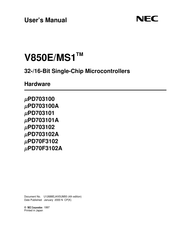
NEC V850E/MS1 UPD703101A User Manual (449 pages)
32-/16-Bit Single-Chip Microcontrollers
Brand:
NEC
| Category:
Microcontrollers
| Size: 2.15 MB
Table of Contents
Table of Contents
13
Chapter 1 Introduction
27
Outline
27
Features
28
Applications
30
Ordering Information
30
Pin Configuration (Top View)
31
Function Block
35
Internal Block Diagram
35
Internal Units
36
Chapter 2 Pin Functions
39
List of Pin Functions
39
Pin Status
47
Description of Pin Functions
49
Pin Input/Output Circuits and Recommended Connection of Unused Pins
65
Pin Input/Output Circuits
67
Chapter 3 Cpu Function
69
Features
69
CPU Register Set
70
Program Register Set
71
System Register Set
72
Operation Modes
74
Operation Mode Specification
75
Address Space
76
CPU Address Space
76
Image
77
Wrap-Around of CPU Address Space
78
Memory Map
79
Area
80
External Expansion Mode
87
Recommended Use of Address Space
89
Peripheral I/O Registers
92
Specific Registers
100
Chapter 4 Bus Control Function
103
Features
103
Bus Control Pins
103
Memory Block Function
104
Bus Cycle Type Control Function
105
Bus Cycle Type Configuration Register (BCT)
105
Bus Access
107
Number of Access Clocks
107
Bus Sizing Function
108
Bus Width
109
Wait Function
113
Programmable Wait Function
113
External Wait Function
114
Relationship between Programmable Wait and External Wait
114
Bus Cycles in Which the Wait Function Is Valid
115
Idle State Insertion Function
117
Bus Hold Function
119
Outline of Function
119
Bus Hold Procedure
120
Operation in Power Save Mode
120
Bus Hold Timing
121
Bus Priority Order
122
Boundary Operation Conditions
122
Program Space
122
Data Space
123
Chapter 5 Memory Access Control Function
125
SRAM, External ROM, External I/O Interface
125
SRAM Connections
125
SRAM, External ROM, External I/O Access
126
Page ROM Controller (ROMC)
130
Features
130
Page ROM Connections
130
On-Page/Off
132
Page ROM Configuration Register (PRC)
134
Page ROM Access
135
DRAM Controller
136
Features
136
DRAM Connections
137
Address Multiplex Function
138
DRAM Configuration Registers 0 to 3 (DRC0 to DRC3)
139
DRAM Type Configuration Register (DTC)
142
DRAM Access
143
DRAM Access During DMA Flyby Transfer
151
Refresh Control Function
153
Self-Refresh Functions
158
Chapter 6 Dma Functions (Dma Controller)
161
Features
161
Configuration
162
Control Registers
163
DMA Source Address Registers 0 to 3 (DSA0 to DSA3)
163
DMA Destination Address Registers 0 to 3 (DDA0 to DDA3)
165
DMA Byte Count Registers 0 to 3 (DBC0 to DBC3)
167
DMA Addressing Control Registers 0 to 3 (DADC0 to DADC3)
168
DMA Channel Control Registers 0 to 3 (DCHC0 to DCHC3)
170
DMA Trigger Factor Registers 0 to 3 (DTFR0 to DTFR3)
171
DMA Disable Status Register (DDIS)
173
DMA Restart Register (DRST)
173
Flyby Transfer Data Wait Control Register (FDW)
174
DMA Bus States
175
Types of Bus States
175
DMAC State Transition
178
Transfer Mode
179
Single Transfer Mode
179
Single-Step Transfer Mode
180
Block Transfer Mode
180
Transfer Types
181
Two-Cycle Transfer
181
Flyby Transfer
185
Transfer Objects
189
Transfer Type and Transfer Objects
189
External Bus Cycle During DMA Transfer
189
DMA Channel Priorities
190
Next Address Setting Function
190
DMA Transfer Start Factors
191
Interrupting DMA Transfer
192
Interruption Factors
192
Forcible Interruption
192
Terminating DMA Transfer
192
DMA Transfer End Interrupt
192
Terminal Count Output
192
Forcible Termination
193
Boundary of Memory Area
194
Transfer of Misalign Data
194
Clocks of DMA Transfer
194
Maximum Response Time to DMA Request
194
One Time Single Transfer with DMARQ0 to DMARQ3
196
Bus Arbitration for CPU
197
Precaution
197
Chapter 7 Interrupt/Exception Processing Function
199
Features
199
Non-Maskable Interrupt
204
Operation
205
Restore
207
Non-Maskable Interrupt Status Flag (NP)
208
Noise Elimination
208
Edge Detection Function
208
Maskable Interrupts
209
Operation
209
Restore
211
Priorities of Maskable Interrupts
212
Interrupt Control Register (Xxicn)
216
In-Service Priority Register (ISPR)
218
Maskable Interrupt Status Flag (ID)
218
Noise Elimination
219
Edge Detection Function
220
Software Exception
222
Operation
222
Restore
223
Exception Status Flag (EP)
224
Exception Trap
225
Illegal Op Code Definition
225
Operation
226
Restore
226
Multiple Interrupt Processing Control
227
Interrupt Latency Time
229
Periods in Which Interrupt Is Not Acknowledged
229
Chapter 8 Clock Generator Functions
231
Features
231
Configuration
231
Input Clock Selection
232
Direct Mode
232
PLL Mode
232
Clock Control Register (CKC)
233
PLL Lockup
234
Power Saving Control
235
Outline
235
Control Registers
237
HALT Mode
238
IDLE Mode
240
Software STOP Mode
242
Clock Output Inhibit Mode
243
Securing Oscillation Stabilization Time
244
Specifying Securing of Oscillation Stabilization Time
244
Time Base Counter (TBC)
246
Chapter 9 Timer/Counter Function (Real-Time Pulse Unit)
247
Features
247
Basic Configuration
248
Timer 1
249
Timer 4
250
Control Registers
254
Timer 1 Operation
262
Count Operation
262
Count Clock Selection
263
Overflow
264
Clearing/Starting Timer by Tclr1N Signal Input
265
Capture Operation
266
Compare Operation
269
Timer 4 Operation
271
Count Operation
271
Count Clock Selection
271
Overflow
271
Compare Operation
272
Application Example
274
Precaution
281
Chapter 10 Serial Interface Function
283
Features
283
Asynchronous Serial Interfaces 0, 1 (UART0, UART1)
284
Features
284
Configuration
285
Control Registers
287
Interrupt Request
294
Operation
295
Clocked Serial Interfaces 0 to 3 (CSI0 to CSI3)
299
Features
299
Configuration
299
Control Registers
301
Basic Operation
304
Transmission by CSI0 to CSI3
306
Reception by CSI0 to CSI3
307
Transmission and Reception by CSI0 to CSI3
308
Example of System Configuration
309
Dedicated Baud Rate Generators 0 to 2 (BRG0 to BRG2)
310
Configuration and Function
310
Baud Rate Generator Compare Registers 0 to 2 (BRGC0 to BRGC2)
313
Baud Rate Generator Prescaler Mode Registers 0 to 2 (BPRM0 to BPRM2)
314
Chapter 11 A/D Converter
315
Features
315
Configuration
315
Control Registers
318
A/D Converter Operation
323
Basic Operation of A/D Converter
323
Operation Mode and Trigger Mode
324
Operation in A/D Trigger Mode
329
Select Mode Operations
329
Scan Mode Operations
331
Operation in Timer Trigger Mode
332
Select Mode Operations
333
Scan Mode Operations
337
Operation in External Trigger Mode
341
Select Mode Operations (External Trigger Select)
341
Scan Mode Operations (External Trigger Scan)
343
Operating Precautions
345
Stopping Conversion Operation
345
External/Timer Trigger Interval
345
Operation of Standby Mode
345
Compare Match Interrupt When in Timer Trigger Mode
345
Timer 1 Functions When in External Trigger Mode
346
Chapter 12 Port Functions
347
Features
347
Port Configuration
348
Port Pin Functions
368
Port 0
368
Port 1
371
Port 2
374
Port 3
377
Port 4
380
Port 5
382
Port 6
384
Port 7
386
Port 8
387
Port 9
391
Port 10
394
Port 11
397
Port 12
401
Port a
403
Port B
405
Port X
407
Chapter 13 Reset Functions
409
Features
409
Pin Functions
409
Initialization
410
CHAPTER 14 FLASH MEMORY ( Μ Μ Μ Μ PD70F3102, 70F3102A)
413
Features
413
Writing by Flash Programmer
413
Programming Environment
414
Communication System
414
Pin Handling
415
MODE3/VPP Pin
415
Serial Interface Pin
415
RESET Pin
417
NMI Pin
417
MODE0 to MODE2 Pins
417
Port Pin
417
WAIT Pin
417
Other Signal Pins
417
Power Supply
418
Programming Method
418
Flash Memory Control
418
Flash Memory Programming Mode
419
Selection of Communication Mode
419
Communication Command
420
Appendix A Register Index
423
Appendix B Instruction Set List
431
General Examples
431
Instruction Set (in Alphabetical Order)
434
Appendix C Index
441
Advertisement
Advertisement
Related Products
NEC V850E/MS1 UPD703100A
NEC V850E/MS1 UPD703102A
NEC UPD703116
NEC UPD703116(A)
NEC UPD703116(A1)
NEC V850ES/SA2 UPD70F3201Y
NEC uPD70F3615
NEC uPD70F3616
NEC uPD70F3743
NEC uPD70F3746
NEC Categories
Monitor
Projector
Server
Telephone
Computer Hardware
More NEC Manuals
Login
Sign In
OR
Sign in with Facebook
Sign in with Google
Upload manual
Upload from disk
Upload from URL