Sign In
Upload
Manuals
Brands
Nokia Manuals
Cell Phone
RM-104 Series
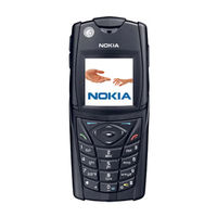
Nokia RM-104 Series Manuals
Manuals and User Guides for Nokia RM-104 Series. We have
3
Nokia RM-104 Series manuals available for free PDF download: Troubleshooting Instructions, Manual, Disassembly Instructions Manual
Nokia RM-104 Series Troubleshooting Instructions (102 pages)
Transceivers
Brand:
Nokia
| Category:
Cell Phone
| Size: 2.24 MB
Table of Contents
Table of Contents
3
RF Troubleshooting
7
Introduction to RF Troubleshooting
7
RF Key Component Placement
8
Fig 1 Component Placement 1
8
RF Test Points
9
Fig 2 Picture of the Assembled PWB with Chambers
9
Receiver
10
Fig 3 Receiver Test Points
10
Transmitter
11
Synthesizer
11
Fig 4 Transmitter Test Points
11
Fig 5 Synthesizer Test Points
11
RF in General
12
Fig 6 RF Block -Diagram
12
Fig 7 RF Power Supply Configuration
13
RF Power Supply Configuration
14
Receiver Verification and Troubleshooting
16
General Instructions for RX Troubleshooting
16
Measuring RX I/Q Signals Using RSSI Reading
16
Fig 8 RSSI Window
17
Measuring RX Performance Using SNR Measurement
18
Measuring Front-End Power Levels Using Spectrum Analyzer
19
Fig 9 Signal Measurement
19
Measuring Analogue RX I/Q Signals Using Oscilloscope
20
Fig 10 Signal Amplitudes
20
Fault Finding Chart of the Receiver
21
Fig 11 RX IQ Signals
21
Fig 12 Receiver Fault Chart 1
22
Fig 13 Receiver Fault Chart 2
23
Fig 14 Receiver Fault Chart 3, 4, 5
23
Fig 15 Receiver Fault Chart 6
24
Fig 16 Receiver Fault Chart 7
24
Rx Signal Paths
25
Antenna Switch (RX/TX Switch)
25
Fig 17 Receiver Fault Chart 8
25
Fig 18 Receiver Fault Chart 9
25
Rx Front-End
26
Fig 19 Block Diagram of Antenna Switch: Left Input Port (Antenna) and Right Output Ports Rx/Tx
26
RX Paths of RF ASIC
27
Transmitter
28
General Instructions for Transmitter Troubleshooting
28
Transmitter Troubleshooting
28
Antenna Switch (TX/RX Switch)
28
GSM850 Transmitter
29
General Instructions for GSM850 TX Troubleshooting
29
Gmsk
29
Edge
30
Fig 20 RF Controls
30
Fault Finding Chart for GSM850 Transmitter
32
Fig 21 RF Controls
32
Gmsk
33
Edge
34
GSM900 Transmitter
34
General Instructions for GSM TX Troubleshooting
34
Gmsk
34
Edge
35
Fig 22 Band Selection
35
Fault Finding Chart for GSM900 Transmitter
36
Fig 23 RF Control Values
36
Gmsk
37
Edge
38
GSM1800 Transmitter
38
General Instructions for GSM1800 TX Troubleshooting
38
Gmsk
38
Edge
39
Fig 24 RF Control Values
39
Fault Finding Chart for GSM1800 Transmitter
40
Fig 25 RF Control Values
40
Gmsk
41
Edge
42
GSM1900 Transmitter
42
General Instructions for GSM1900 TX Troubleshooting
42
Gmsk
42
Edge
43
Fig 26 RF Control Values
43
Fault Finding Chart for GSM1900 Transmitter
44
Fig 27 RF Control Values
44
Gmsk
45
Edge
46
Synthesizer
47
Check Synthesizer Operation
47
Reference Oscillator 26 Mhz (VCTCXO)
48
Fig 28 Typical Feature Tuning Curve for the Matshushita VCO
48
Voltage Controlled Oscillator (VCO)
49
Fault Finding Chart for PLL Synthesizer
50
Pictures of Synthesizer Signals
51
Fig 29 26 Mhz at G501 Pin out
51
Fig 30 26 Mhz RFCLK at R420/C420
51
Fig 31 VCO Output, 1800 Band, RX On, Continuous Output
52
Frequency Tables
53
Gsm850
53
GSM900 (Including EGSM900)
54
Gsm1800
55
Gsm1900
57
DC Supply Current Check
59
Fig 32 DC Power Supply Diagram
59
Baseband Troubleshooting
60
BB Measurement Points
60
Fig 33 NPL-4/5 BB Measurement Points, Top
60
Fig 34 NPL-4/5 BB Measurement Points, Bottom
61
Troubleshooting Diagrams
62
Phone Is Dead
63
Phone Is Jammed 1
64
Phone Is Jammed 2
65
Flash Faults 1
66
Flash Faults 2
67
SIM Card Faults
68
Charger Faults
69
Display Faults 1
70
Display Faults 2
71
Audio Fault1
72
Audio Fault 2
73
Audio Fault 3
74
Keyboard Faults 1
75
Keyboard Faults 2
76
Keyboard Faults 3
77
Keyboard Faults 4
78
Keyboard Faults 5
79
Accessory Faults1
80
Fig 35 MBUS
81
Accessory Faults 2
82
Fig 36 ACI Diagram
83
Flashlight Faults
84
Self Tests
85
FCI Troubleshooting
86
IHF Troubleshooting
88
Compass Troubleshooting
89
Calibration 1
90
Calibration 2
91
Sensor Problems 1
92
Start Calibration
93
Fig 37 Testpoints
94
Magic Troubleshooting
96
FM Radio Troubleshooting
97
FM Radio Component Layout
97
Fig 38 Component Placement
97
Fig 39 Trace Layout
98
FM Radio Troubleshooting Diagram
99
Notes to "FM Radio Troubleshooting Diagram
99
Advertisement
Nokia RM-104 Series Manual (86 pages)
Transceivers, System Module and User Interface
Brand:
Nokia
| Category:
Cell Phone
| Size: 0.94 MB
Table of Contents
Table of Contents
3
Glossary of Terms
7
Introduction
10
Electrical Modules
10
Interconnection Diagram
10
Fig 1 Interconnection Diagram
10
Temperature Conditions
11
Humidity
11
System Module
12
Baseband Module
12
Technical Summary
13
Fig 2 Baseband Blocks
13
Pwb
15
DC Characteristics
15
Fig 3 PWB Vias
15
External and Internal Signals and Connections
18
Fig 4 Power Distribution Diagram
18
UI Board Interface Signals
24
Display Interface Signals
25
System Connector Interface Signals
26
SIM Interface Signals
27
FCI Interface Signals
28
Camera Interface Signals
28
FM Radio Interface Signals
29
Compass Interface Signals
30
Functional Description
31
Modes of Operation
31
No Supply
31
Backup
31
Acting Dead
31
Active
31
Sleep Mode
32
Charging
33
Power up and Reset
33
Power up with PWR Key
34
Power up When Charger Is Connected
34
Battery
34
Fig 5 Battery Pack Contacts
35
A/D Channels
36
Digital Camera
36
FM Radio
37
Fig 6 Camera Connections to Baseband
37
Fig 7 FM Radio Audio-, Antenna- and Digital Interface Connections
37
Electrical Compass
38
Thermometer
38
Fig 8 Baseband and Compass Interface
38
Backup Battery
39
SIM Interface
39
Fig 9 Ambient Temperature Sensor Interface to BB
39
FCI (Functional Cover Interface)
40
Fig 10 UPP/UEMEK SIM Interface Connections
40
Memory
41
Fig 11 FCI Interface
41
Fig 12 FCI Connector Pin Order on PWB
41
External Memory
42
Compass
43
Earth Magnetic Field
43
Heading Angle or Azimuth (A)
44
Inclination (D)
44
Declination (L)
44
Fig 13 Earth's Magnetic Field
44
Tilt (S)
45
Fig 14 Earths's Magnetic Field Components
45
HW Block Diagram
46
HW Block Functions
46
Fig 15 Block Diagram
46
Magnetometer Sensor
48
Main Features
48
Block Diagram
49
Magnetometer Control Interface
49
Pin Assignment
49
Fig 16 Magnetometer Sensor Block Diagram
49
Test Circuitry
51
Magic ASIC
51
Main Features
52
Block Diagram and Functional Descriptions
52
Magic Control Interface
53
Pin Assignment
53
Magic ASIC Interface - Magnetometer Sensor
53
Magic ASIC - UPP Interface
54
Magic ASIC - UEME Interface
55
Magic ASIC - UPP - External Power Supply Interface
55
Magic - Magnetometer Sensor Interface for Constant Current Driver
56
Power Supplies
56
Introduction
56
Using VIO for DVDD Supply
56
Using External Regulator for AVDD
56
Compass and Phone Basics
57
Phone Directions
57
General Description
58
Operation Modes
58
Compass Function Main Features
58
Compass Display Menu
58
Compass Display Results
58
Compass Calibration SW
59
User Assisted Calibration
59
Compass Declination Menu
59
Testpoints
60
Set/Reset
60
Vbridge
60
Channel Output a
60
Channel Output B
60
Service Software Interface (Phoenix)
61
Manual Calibration
61
Performance
62
Calibration Basics
62
Calibration Process Flow
63
Compass Digital Values, Limit Values
63
Clock Distribution
65
User Interface
66
Display
66
UI Board
67
Power Supply for Leds
68
Keyboard Leds Driver
69
Display and Air Bubble LED Driver
69
Blinking
70
Off
70
On, but Not Blinking
70
RM-104 Standby Light Design
70
Flashlight Leds Driver
71
Internal Microphone
71
Internal Speaker
73
Ihf
73
Headset Connections
74
Vibra
75
RF Module
76
RF Frequency Plan
77
DC Characteristics
78
Regulators
78
Power Distribution
79
RF Characteristics
80
RF Block Diagram
81
RF Block Diagram NPL-4/5 & RM-104
81
Frequency Synthesizers
82
Receiver
82
Transmitter
83
Antenna Switch Module
84
Power Amplifier
85
AFC Function
86
Antenna
86
RF ASIC Helgo
86
Nokia RM-104 Series Disassembly Instructions Manual (6 pages)
Transceivers
Brand:
Nokia
| Category:
Cell Phone
| Size: 0.44 MB
Advertisement
Advertisement
Related Products
Nokia RM-1042
Nokia RM-1043
Nokia RM-1045
Nokia RM-1041
Nokia RM-1040
Nokia RM-1087
Nokia RM-100
Nokia RM-1017
Nokia RM-1019
Nokia RM-1025
Nokia Categories
Cell Phone
Headsets
Transceiver
Telephone
Handhelds
More Nokia Manuals
Login
Sign In
OR
Sign in with Facebook
Sign in with Google
Upload manual
Upload from disk
Upload from URL