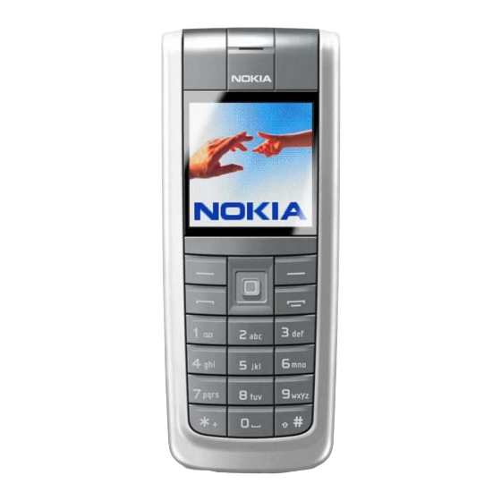
Nokia 6235 Antenna Description And Troubleshooting
Mobile terminals
Hide thumbs
Also See for 6235:
- User manual (233 pages) ,
- Troubleshooting manual (68 pages) ,
- Baseband description and troubleshooting (48 pages)
Summary of Contents for Nokia 6235
- Page 1 Nokia Customer Care 6235/6235i/6236i (RM-60) Mobile Terminals Antenna Description and Troubleshooting ©2005 Nokia Corporation Issue 1 04/2005 Company Confidential...
-
Page 2: Table Of Contents
6235/6235i/6236i (RM-60) Antenna Description and Troubleshooting Contents Page Introduction ..............................3 Visual Quality Requirements ........................3 Failures and Corrective Measures ......................3 Antenna Position ............................3 Internal Antenna ............................3 Damaged RF Feed, Ground Pins, or IHF Speaker Pins ................ 4 Damaged GPS antenna, pins, or heat stake .................. -
Page 3: Introduction
6235/6235i/6236i (RM-60) Nokia Customer Care Antenna Description and Troubleshooting Introduction The mobile terminal incorporates an internal antenna. This antenna arrangement is used for AMPS/CELL and PCS frequency bands. The internal antenna assembly consists of a Planar Inverted-F Antenna (PIFA) used for the cellular engine and an Inverted-F antenna (IFA) used for the GPS engine, which is placed on the side of internal antenna body. -
Page 4: Damaged Rf Feed, Ground Pins, Or Ihf Speaker Pins
6235/6235i/6236i (RM-60) Antenna Description and Troubleshooting An integrated hands-free (IHF) mini speaker is integrated inside the plastic. Main antenna radiator (PIFA) GPS antenna radiator (IFA) Figure 2: Internal antenna Note: The GPS antenna is only functional on models that support the GPS engine. -
Page 5: Damaged Gps Antenna, Pins, Or Heat Stake
6235/6235i/6236i (RM-60) Nokia Customer Care Antenna Description and Troubleshooting • If the ground pin of the GPS antenna does not touch the PWB, the GPS antenna gain may degrade by more than 5 dB. • If either the RF feed pin or ground pin are broken or bent such that either pin does not touch the PWB, then replace the internal antenna. -
Page 6: Obstructed Ihf Speaker, Rf Feed, And Ground Pads
6235/6235i/6236i (RM-60) Antenna Description and Troubleshooting Obstructed IHF Speaker, RF Feed, and Ground Pads The antenna module connects to the PWB at specific places. These are show in Figure Ground pad for RF feed pad for GPS RF connector GPS antenna... -
Page 7: Cdma Or Gps Rf Connector Failure
6235/6235i/6236i (RM-60) Nokia Customer Care Antenna Description and Troubleshooting CDMA OR GPS RF Connector Failure CDMA and GPS use the same type of RF connector. The RF connector fails when it does not connect the RF input to the RF output. -
Page 8: Grounding Of Display Frame
6235/6235i/6236i (RM-60) Antenna Description and Troubleshooting Grounding of Display Frame The display frame is grounded to the PWB through two ground panels. The display frame grounding impacts the radiation performance of the mobile terminal. Display frame grounding Display frame through screws... -
Page 9: Calibration Factor For Pcs1900 Frequency
6235/6235i/6236i (RM-60) Nokia Customer Care Antenna Description and Troubleshooting Calibration Factor for PCS1900 Frequency Use a call box to turn on the transmitter of the mobile terminal with a known output power and antenna performance at the maximum output power (all bits up). Measure the transmitted power on the RF connector and through a coupler at CDMA PCS channel 1175. -
Page 10: Measurement Procedure For Gps Antenna
6235/6235i/6236i (RM-60) Antenna Description and Troubleshooting has to be measured separately for every coupler because the path losses vary depending on the setup, cables, and attenuator. Measurement Procedure for GPS Antenna 1. Place the mobile terminal in the test adapter (DA-54) with the display up.


