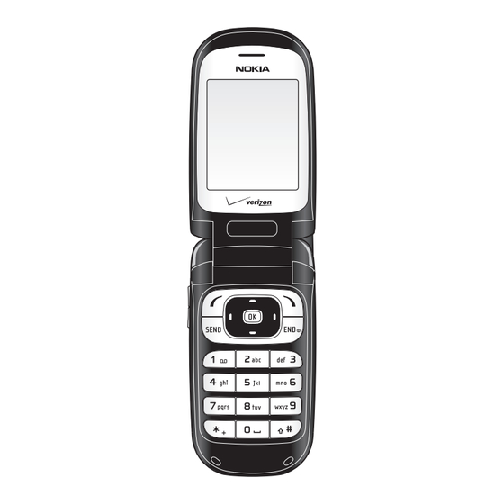
Nokia 2366i Assembly
Mobile terminals
Hide thumbs
Also See for 2366i:
- Manual del usuario (121 pages) ,
- User manual (113 pages) ,
- Rf description and troubleshooting (58 pages)
Summary of Contents for Nokia 2366i
- Page 1 Nokia Customer Care 2366i (RM-155) Mobile Terminals Assembly Issue 2 - February 2007 Company Confidential...
-
Page 2: Table Of Contents
2366i (RM-155) Assembly Nokia Customer Care Contents Page Safety Information ............................3 ESD Protection ............................. 3 Assembly Instructions ........................... 4 1. Install the Earpiece ..........................4 2. Install the External LCD Display ......................4 3. Install the Main LCD Display ....................... 5 4. -
Page 3: Safety Information
ESD protection. • ESD-protected spare part packages MUST NOT be opened/closed outside an EPA. For more detailed information about ESD protection and EPAs, contact your local Nokia Customer Care representative. Issue 2 - February 2007... -
Page 4: Assembly Instructions
2366i (RM-155) Assembly Nokia Customer Care Assembly Instructions Use the following steps to assemble the mobile terminal. 1. Install the Earpiece Install a new adhesive onto the earpiece. Install the earpiece into the A-cover. Note: Do not bend or damage the contacts. With the hinge to the left, the contacts should be on the downward side. -
Page 5: Install The Main Lcd Display
2366i (RM-155) Nokia Customer Care Assembly Connect the earpiece flex connector. 3. Install the Main LCD Display Place the main LCD display face-down. Align the metal frame such that it engages the six tabs on the display. Tab (6) Connect the main LCD flex cable. -
Page 6: Install The Upper Ui Into The B-Cover
2366i (RM-155) Assembly Nokia Customer Care 4. Install the Upper UI into the B-cover Install the main flex cable into the slot. Install the upper UI assembly into the A-cover and engage the locking tabs. Connect the main flex connector. -
Page 7: Assemble The Hinge
2366i (RM-155) Nokia Customer Care Assembly 5. Assemble the Hinge Align the slots and combine the the C-cover and B-cover. Use tweezers to open the flip damper and allow the main flex cable to slide freely through. Ensure that the flip damper is properly seated after routing the main flex cable. - Page 8 2366i (RM-155) Assembly Nokia Customer Care Hold the assembly as shown. Engage the left hinge. Flex the C-cover and partially engage the right hinge. Fully open the flip cover. The right hinge snaps fully into place. Note: The hinge should operate smoothly. If there is any binding, disengage the right hinge and ensure that the main flex cable is correctly routed and that the flip damper is correctly seated.
-
Page 9: Install The A-Cover
2366i (RM-155) Nokia Customer Care Assembly 6. Install the A-Cover Engage the A-cover with the B-cover at the earpiece end. Apply pressure equally to both sides until the locking tabs engage with a click. Rotate the phone 180 degrees and apply pressure equally to both sides of the hinge end until the locking tabs engage with a click. -
Page 10: Install The Keymat
2366i (RM-155) Assembly Nokia Customer Care 8. Install the Keymat Press the keymat into position, ensuring that the tabs engage the locating posts on the cover. 9. Connect the Flex Connector Connect the flex connector to the PWB. Attach the adhesive ground connector to the pad on the PWB. -
Page 11: Install The Main Pwb Into The C-Cover
2366i (RM-155) Nokia Customer Care Assembly 10. Install the Main PWB into the C-Cover Install the sidekey switch assembly into the slot behind the sidekey. Install the main PWB onto the C-cover, ensuring that the locking tabs engage with a click. -
Page 12: Install The Uhj Cover
2366i (RM-155) Assembly Nokia Customer Care 11. Install the UHJ Cover Carefully align and press down on the flex connector until it snaps to the PWB. 12. Install the Antenna Insert the antenna. Install the RF grommet. Page 12 Company Confidential... -
Page 13: Install The Microphone Module
2366i (RM-155) Nokia Customer Care Assembly 13. Install the Microphone Module Install the microphone module into the D-cover, ensuring that no damage occurs to the contacts. 14. Install the DC Jack Install the DC jack into the D-cover, ensuring that no damage occurs to the contacts. - Page 14 2366i (RM-155) Assembly Nokia Customer Care Apply pressure to the edges to engage the locking tabs. Install the four #4 Torx screws. Set the correct torque: 20 Ncm (±2 Ncm) / 500 RPM. Tighten the screws in the order shown.
-
Page 15: Install The Battery Cover
2366i (RM-155) Nokia Customer Care Assembly 16. Install the Battery Cover Install the battery cover and slide it toward the antenna end until the cover locks with a click. The assembly procedure is complete. Issue 2 - February 2007 Company Confidential... - Page 16 2366i (RM-155) Assembly Nokia Customer Care This page left intentionally blank. Page 16 Company Confidential Issue 2 - February 2007...


