Sign In
Upload
Manuals
Brands
NEC Manuals
Microcontrollers
MuPD78F0136H
NEC MuPD78F0136H Manuals
Manuals and User Guides for NEC MuPD78F0136H. We have
1
NEC MuPD78F0136H manual available for free PDF download: User Manual
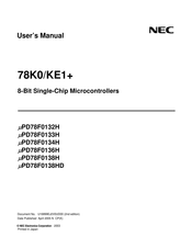
NEC MuPD78F0136H User Manual (540 pages)
8-Bit Single-Chip Microcontrollers, 78K0/KE1Plus
Brand:
NEC
| Category:
Microcontrollers
| Size: 3.21 MB
Table of Contents
Table of Contents
9
Chapter 1 Outline
16
Features
16
Applications
17
Ordering Information
18
Pin Configuration (Top View)
19
Kx1 Series Lineup
22
78K0/Kx1, 78K0/Kx1+ Product Lineup
22
V850Es/Kx1, V850Es/Kx1+ Product Lineup
25
Block Diagram
28
Outline of Functions
29
Chapter 2 Pin Functions
32
Pin Function List
32
Description of Pin Functions
36
P00 to P06 (Port 0)
36
P10 to P17 (Port 1)
37
P20 to P27 (Port 2)
38
P30 to P33 (Port 3)
38
P40 to P43 (Port 4)
38
P50 to P53 (Port 5)
38
P60 to P63 (Port 6)
39
P70 to P77 (Port 7)
39
P120 (Port 12)
39
P130 (Port 13)
39
P140 and P141 (Port 14)
39
Av Ref
40
Av Ss
40
Reset
40
X1 and X2
40
XT1 and XT2
40
VDD and EV DD
40
VSS and EV SS
40
FLMD0 and FLMD1
40
Pin I/O Circuits and Recommended Connection of Unused Pins
41
Chapter 3 Cpu Architecture
45
Memory Space
45
Internal Program Memory Space
52
Internal Data Memory Space
53
Special Function Register (SFR) Area
54
Data Memory Addressing
54
Processor Registers
60
Control Registers
60
General-Purpose Registers
64
Special Function Registers (Sfrs)
65
Instruction Address Addressing
70
Relative Addressing
70
Immediate Addressing
71
Register Addressing
72
Table Indirect Addressing
72
Operand Address Addressing
73
Implied Addressing
73
Register Addressing
74
Direct Addressing
75
Short Direct Addressing
76
Special Function Register (SFR) Addressing
77
Register Indirect Addressing
78
Based Addressing
79
Based Indexed Addressing
80
Stack Addressing
81
Chapter 4 Port Functions
82
Port Functions
82
Port Configuration
84
Port 0
85
Port 1
89
Port 2
94
Port 3
95
Port 4
97
Port 5
98
Port 6
99
Port 7
100
Port 12
101
Port 13
102
Port 14
103
Registers Controlling Port Function
104
Port Function Operations
108
Writing to I/O Port
108
Reading from I/O Port
108
Operations on I/O Port
108
Chapter 5 Clock Generator
109
Functions of Clock Generator
109
Configuration of Clock Generator
109
Registers Controlling Clock Generator
111
System Clock Oscillator
118
High-Speed System Clock Oscillator
118
Subsystem Clock Oscillator
118
When Subsystem Clock Is Not Used
121
Ring-OSC Oscillator
121
Prescaler
121
Clock Generator Operation
122
Time Required to Switch between Ring-OSC Clock and High-Speed System Clock
129
Time Required for CPU Clock Switchover
130
Clock Switching Flowchart and Register Setting
131
Switching from Ring-OSC Clock to High-Speed System Clock
131
Switching from High-Speed System Clock to Ring-OSC Clock
132
Switching from High-Speed System Clock to Subsystem Clock
133
Switching from Subsystem Clock to High-Speed System Clock
134
Register Settings
135
Chapter 6 16-Bit Timer/Event Counters 00 and 01
136
Functions of 16-Bit Timer/Event Counters 00 and 01
136
Configuration of 16-Bit Timer/Event Counters 00 and 01
137
Registers Controlling 16-Bit Timer/Event Counters 00 and 01
142
Operation of 16-Bit Timer/Event Counters 00 and 01
153
Interval Timer Operation
153
PPG Output Operations
156
Pulse Width Measurement Operations
159
External Event Counter Operation
167
Square-Wave Output Operation
170
One-Shot Pulse Output Operation
172
Cautions for 16-Bit Timer/Event Counters 00 and 01
177
Chapter 7 8-Bit Timer/Event Counters 50 and 51
180
Functions of 8-Bit Timer/Event Counters 50 and 51
180
Configuration of 8-Bit Timer/Event Counters 50 and 51
182
Registers Controlling 8-Bit Timer/Event Counters 50 and 51
184
Operations of 8-Bit Timer/Event Counters 50 and 51
189
Operation as Interval Timer
189
Operation as External Event Counter
191
Square-Wave Output Operation
192
PWM Output Operation
193
Cautions for 8-Bit Timer/Event Counters 50 and 51
197
Chapter 8 8-Bit Timers H0 and H1
198
Functions of 8-Bit Timers H0 and H1
198
Configuration of 8-Bit Timers H0 and H1
198
Registers Controlling 8-Bit Timers H0 and H1
202
Operation of 8-Bit Timers H0 and H1
208
Operation as Interval Timer/Square-Wave Output
208
Operation as PWM Output Mode
211
Carrier Generator Mode Operation (8-Bit Timer H1 Only)
217
Chapter 9 Watch Timer
224
Functions of Watch Timer
224
Configuration of Watch Timer
226
Register Controlling Watch Timer
226
Watch Timer Operations
228
Watch Timer Operation
228
Interval Timer Operation
229
Cautions for Watch Timer
230
Chapter 10 Watchdog Timer
231
Functions of Watchdog Timer
231
Configuration of Watchdog Timer
233
Registers Controlling Watchdog Timer
234
Operation of Watchdog Timer
237
Watchdog Timer Operation When "Ring-OSC Cannot be Stopped" Is Selected by Option Byte
237
Watchdog Timer Operation When "Ring-OSC Can be Stopped by Software" Is Selected by Option Byte
238
Watchdog Timer Operation in STOP Mode (When "Ring-OSC Can be Stopped by Software" Is Selected by Option Byte)
239
Watchdog Timer Operation in HALT Mode (When "Ring-OSC Can be Stopped by Software" Is Selected by Option Byte)
241
Chapter 11 Clock Output/Buzzer Output Controller
242
Functions of Clock Output/Buzzer Output Controller
242
Configuration of Clock Output/Buzzer Output Controller
243
Register Controlling Clock Output/Buzzer Output Controller
243
Clock Output/Buzzer Output Controller Operations
245
Clock Output Operation
245
Operation as Buzzer Output
245
Chapter 12 A/D Converter
246
Functions of A/D Converter
246
Configuration of A/D Converter
247
Registers Used in A/D Converter
249
A/D Converter Operations
254
Basic Operations of A/D Converter
254
Input Voltage and Conversion Results
256
A/D Converter Operation Mode
257
How to Read A/D Converter Characteristics Table
260
Cautions for A/D Converter
262
Chapter 13 Serial Interface Uart0
267
Functions of Serial Interface UART0
267
Configuration of Serial Interface UART0
268
Registers Controlling Serial Interface UART0
271
Operation of Serial Interface UART0
276
Operation Stop Mode
276
Asynchronous Serial Interface (UART) Mode
277
Dedicated Baud Rate Generator
283
Chapter 14 Serial Interface Uart6
288
Functions of Serial Interface UART6
288
Configuration of Serial Interface UART6
292
Registers Controlling Serial Interface UART6
295
Operation of Serial Interface UART6
304
Operation Stop Mode
304
Asynchronous Serial Interface (UART) Mode
305
Dedicated Baud Rate Generator
319
Chapter 15 Serial Interfaces Csi10 and Csi11
326
Functions of Serial Interfaces CSI10 and CSI11
326
Configuration of Serial Interfaces CSI10 and CSI11
327
Registers Controlling Serial Interfaces CSI10 and CSI11
329
Operation of Serial Interfaces CSI10 and CSI11
335
Operation Stop Mode
335
3-Wire Serial I/O Mode
336
Chapter 16 Multiplier/Divider
346
Functions of Multiplier/Divider
346
Configuration of Multiplier/Divider
346
Register Controlling Multiplier/Divider
350
Operations of Multiplier/Divider
351
Multiplication Operation
351
Division Operation
353
Chapter 17 Interrupt Functions
355
Interrupt Function Types
355
Interrupt Sources and Configuration
355
Registers Controlling Interrupt Functions
359
Interrupt Servicing Operations
367
Maskable Interrupt Acknowledgement
367
Software Interrupt Request Acknowledgement
369
Multiple Interrupt Servicing
370
Interrupt Request Hold
373
Chapter 18 Key Interrupt Function
374
Functions of Key Interrupt
374
Configuration of Key Interrupt
374
Register Controlling Key Interrupt
375
Chapter 19 Standby Function
376
Standby Function and Configuration
376
Standby Function
376
Registers Controlling Standby Function
378
Standby Function Operation
380
HALT Mode
380
STOP Mode
385
Chapter 20 Reset Function
389
Register for Confirming Reset Source
396
Chapter 21 Clock Monitor
397
Functions of Clock Monitor
397
Configuration of Clock Monitor
397
Registers Controlling Clock Monitor
398
Operation of Clock Monitor
399
Chapter 22 Power-On-Clear Circuit
404
Functions of Power-On-Clear Circuit
404
Configuration of Power-On-Clear Circuit
405
Operation of Power-On-Clear Circuit
405
Cautions for Power-On-Clear Circuit
406
Chapter 23 Low-Voltage Detector
408
Functions of Low-Voltage Detector
408
Configuration of Low-Voltage Detector
408
Registers Controlling Low-Voltage Detector
409
Operation of Low-Voltage Detector
411
Cautions for Low-Voltage Detector
415
Chapter 24 Option Byte
418
Chapter 25 Rom Correction
419
Functions of ROM Correction
419
Configuration of ROM Correction
419
Register Controlling ROM Correction
421
ROM Correction Usage Example
422
ROM Correction Application
423
Program Execution Flow
426
Cautions for ROM Correction
428
Chapter 26 Flash Memory
429
Internal Memory Size Switching Register
430
Internal Expansion RAM Size Switching Register
431
Writing with Flash Programmer
432
Programming Environment
436
Communication Mode
436
Connection of Pins on Board
439
FLMD0 Pin
439
FLMD1 Pin
439
Serial Interface Pins
440
RESET Pin
442
Port Pins
442
Other Signal Pins
442
Power Supply
442
Programming Method
443
Controlling Flash Memory
443
Flash Memory Programming Mode
444
Selecting Communication Mode
445
Communication Commands
446
Flash Memory Programming by Self-Writing
447
Registers Used for Self-Programming Function
448
Boot Swap Function
452
Outline of Boot Swap Function
452
Memory Map and Boot Area
453
CHAPTER 27 ON-CHIP DEBUG FUNCTION ( Μ PD78F0138HD ONLY)
459
Chapter 28 Instruction Set
460
Conventions Used in Operation List
460
Operand Identifiers and Specification Methods
460
Description of Operation Column
461
Description of Flag Operation Column
461
Operation List
462
Instructions Listed by Addressing Type
470
Chapter 29 Electrical Specifications
473
Chapter 30 Package Drawings
489
Chapter 31 Recommended Soldering Conditions
494
Chapter 32 Cautions for Wait
495
Cautions for Wait
495
Peripheral Hardware that Generates Wait
496
Example of Wait Occurrence
497
Appendix A Development Tools
498
Software Package
501
Language Processing Software
501
A.1 Software Package
501
Control Software
502
Flash Memory Writing Tools
502
A.3 Control Software
502
Debugging Tools (Hardware)
503
When Using In-Circuit Emulator QB-78K0KX1H
503
When Using On-Chip Debug Emulator QB-78K0MINI
504
Debugging Tools (Software)
504
Appendix B Notes on Target System Design
505
Appendix C Register Index
507
Register Index (in Alphabetical Order with Respect to Register Names)
507
Register Index (in Alphabetical Order with Respect to Register Symbol)
511
Appendix D List of Cautions
515
Appendix E Revision History
539
Major Revisions in this Edition
539
Advertisement
Advertisement
Related Products
NEC MuPD78F0132H
NEC MuPD78F0133H
NEC MuPD78F0138H
NEC MuPD78F0134H
NEC MuPD78F0138HD
NEC MuPD754202
NEC MuPD754144
NEC MuPD70F3187
NEC Mu754244
NEC Mu754202A
NEC Categories
Monitor
Projector
Server
Telephone
Computer Hardware
More NEC Manuals
Login
Sign In
OR
Sign in with Facebook
Sign in with Google
Upload manual
Upload from disk
Upload from URL